Gravity Separator 12 Ft. Place determine the selection and design of equipment.

Importance Of Liquid Distributors Part 1 Mach Engineering
As the TUMWelChem Cell Model includes liquid distribution characteristics for different types of packing and hydraulic calculations it renders more detailed investigations and optimizations.

. My experience is that such tests are essential. β ratio of hole to the perforated pipe inside diameter specified earlier as a value between 015 to 020 Y 037 value of Y calculated using eqn i with ΔP o P equal to 037. Connect this point to the point where the equilibrium cure and the feed line.
Fq-1 5 Upper Operating Line 3. Minimum hole diameter 12-in. A typical liquid head level in a v-notch distributor is 13in 2575mm over the entire operating range while a more standard orifice distributor will maintain a head of 312in 75300mm.
What should be verified is the evenness homogeneity of the liquid distribution m3hr of liquid per m2 of section at different areas and at least at nominal and minimum flow rate. Liquid Distributor is used in a packed column to distribute liquid uniformly. 800-231-0077 14211 Industry Street Houston TX 77053 TEL.
8 Can employ a high concentration slurry as scrubbing liquid. The dimensioning of liquid distributors In the dimensioning of liquid distributors not only the discharge coefficient but also other design determining criteria have to be taken into account. P Pressure at the inlet of the gas distributor kPa abs psia k ratio of specific heats C p C v.
In that manner first the minimum liquid head h min above a discharge hole of a liquid distributor must be determined. A distributor with a side hole q80 and pipe guidance system creates the best distribution pattern where empty spaces are at a minimum. Save Save Liquid Distributor Design For Later.
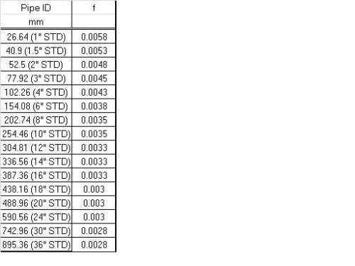
And h PD is the distributor head loss on the vapor side in. Q BA 2gP 1179d2P121 Where q flow rate per perforation gpm B orifice coefficient assumed as. Liquid maldistribution is a major issue in the design of packed columns.
A distributor with a base hole q60 generates a concentrated area below the trough. A distributor with a free overflow q 40 only saturates the line between the trough with water. Liquid distributors are a key component to optimal performance in packed distillation columns.
1 SCOPE This Guide deals with the design and rating of packed distillation columns. The diameter of the droplets is a critical parameter. Operating Principles The incoming gas is accelerated to a high velocity at the scrubbers throat where it comes into contact with the scrubbing.
Maximum hole diameter 02 times inside diameter of distributor. In atm x 224141 0234499 CumSec. Draw the operating line for the enriching section.
H O is the orifice head in. To achieve an intensive mass transfer between the phases the liquid should be distributed equally across the packed column area. 0 ratings 0 found this document useful 0 votes 220 views 3 pages.
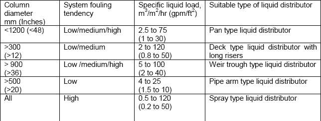
Perforated-plate and trough-type distributors with liquid discharge are recom-mended for moderate liquid loads viz. And allow flow rates of about 005-05 1h through each outlet. 13 mm to avoid plugging and to limit the number of holes to a reasonable value.
13 mm holes may be too small. 7 Temperature and corrosion resistant construction is available. Liquid Distributors An Important Tower Internal Part 1 Liquid distributors are an important component of column internals.
Liquid Viscosity. UL 1 m3m2h. First find the desired top product composition on the x-axis and locate the corresponding point on the forty-five degree line.
The volumetric flow rate through. In very clean service smaller holes may be considered but in severely fouling service 12-in. The unit discharge rate q from each of the perforations is governed by the size of the perforation and the static pressure at its respective location along the pipe.
They provide adequate distribution of the liquid onto the packed bed and structured packing. Liquid leaving 00420Kgs Inlet liquid flow rate comp. It serves to overcome.
In a gravity head distributor this is the sum of the two components. Since liquid head above the orifice is a major component of flow uniformity the lower head distributors typically have a lower-quality distribution than higher head designs. Liquid distributor test for columns.
35 Cp 00035 NSecSqm Gas Density Calculation. In determining the settling velocity in a liquid-liquid disper-. The last requirement simplifies the calculation.
Removed 05 000497 Using 000497 as ordinate 1471 004 from graph Therefore G 004 05 16665 Tower cs area 01667 cs area mass flow rate G Tower diameter 04607m 4607mm 500mm Corresponding cs area 01963 m3s x 273 kmols x T in kelvin x 10 atm x 224. In this work a liquid distributor design method is presented which considers the interaction of the liquid distributor and the packing with the TUMWelChem Cell Model. 6 Simple open design has low potential for build-up and pluggage.
Here the flow velocity of the. H OA h O h PD 1 where h OA is the total liquid head in the liquid distributor in. Their design is commonly based on the drip point density.
For a good performance of the packing large scale maldistribution has to be avoided. Of gas 2945 gmole Gas in flow rate 02778 2945 00094 Kmolsec Kmolesec x T in K 27315 x 1 atm pr. Liquid distributor test for columns.
This paper analyzes liquid distribution in a 0634 m random packed column. It covers neither guidance on the selection of trays and packings nor some aspects of their performance characteristics. The driving force promot-ing coalescence is gravity and in a given system is proportional to r g r being the density difference between the two liq-uid phases.
Siretb Chemical 17 May 10 0236. Profiled-slot distributors per-mit liquid loads of uL 05-200 m3m2h and the flow rate through each outlet is higher than 2 1h. With a proper design of the distributor this can be.
Learn about different types of liquid distributors and its working mechanism in. This Guide has been prepared for GBH Enterprises. Advice on both of these is given in GBHE- PEG-MAS-610 - Selection of Internals for.
2
Column Internals Explained Part 2 Separation Technologies

Column Internals Explained Part 2 Separation Technologies

Liquid Distributors Importance Part 2 Mach Engineering
Perforated Pipe Distributor Sizing Calculations Cheresources Com Community
2
2

Importance Of Liquid Distributors Part 1 Mach Engineering
0 comments
Post a Comment